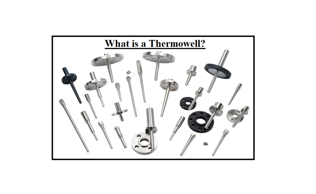
What is a Thermowell? A thermocouple is a temperature measuring device that is used to determine the temperature of a process. A thermowell is a framework that surrounds and protects the thermocouple (or RTD) probe from process elements such as fluid flow rates and caustic or deteriorating chemicals. Thermowells are also utilized to keep pressure boundaries in systems in good shape.
What is a Thermowell?
Temperature sensors such as thermistors, thermocouples, and bimetal thermometers are protected by thermowell against damage caused by material velocity, high pressure, and corrosion. They also extend the sensor’s life, allow for sensor replacement without depleting the system, and lower the risk of contamination. To ensure integrity, thermowell built for high-pressure applications are typically machined from bar stock. Smaller thermowell for low-pressure applications can be made from a tube with one end welded shut.
Thermowells can be a pain to design and maintain, but new advancements have eased some long-standing issues, and other measuring methods can completely eliminate them. Which method is the most effective for you?
Temperature measurement presents unique issues in the field of process instrumentation since a thermowell is required to shield the temperature measurement sensor from harsh process conditions. As a result, the sensor is removed from the process for monitoring, which has an influence on response time and accuracy.
A resistance temperature detector (RTD) is typically made up of a platinum element with connected leads that is housed in a stainless-steel sheath for mechanical and electrical protection. A thermocouple is typically more mechanically resistant, but it still needs to be protected. To achieve an equilibrium temperature between the sensor and the surrounding process, heat from the process must pass through the protective components and any internal insulation.
This heat flow takes time, therefore, there is a lag between when the process temperature changes and when the automation system notices it. The sensor’s small enclosure, which is typically 5 to 7 mm in diameter, is rarely positioned in such a way that it comes into direct contact with the process. A thermowell (see Figure below) is used in most processes to isolate the sensor assembly so that it can be extended into the process without coming into direct contact with it. Visit here to see the principle of a thermowell.
A thermowell is a device that mounts through the wall of a vessel or pipe and extends into the process fluid to a temperature measurement point. The sensor is put into the thermowell from the outside, allowing it to be accessed without shutting down the process. Heat transfers through the thermowell’s wall and eventually to the sheath and sensor since it is exposed to the process fluid. When equilibrium is reached, the sensor provides a measurement that represents the fluid process temperature.
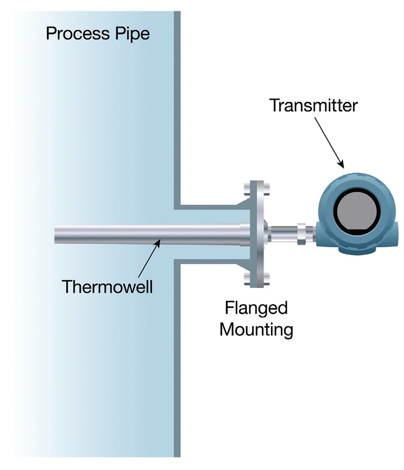
If the temperature of the process fluid changes, the new temperature must travel through all of those layers. This can take anywhere from a few seconds to many minutes, depending on the application. Because few systems undergo abrupt temperature fluctuations, this setup is suitable for the majority of real-world applications.
The Tradeoffs of a Thermowell Selection
Often, the process engineer will indicate where a temperature reading should be taken. The sensor, for example, should be positioned in the pipe coming out of a reactor and the reading is taken from the pipe’s center. As a result, the thermowell insertion length must be half the pipe’s internal diameter.
In normal operation, the process engineer will define how much and how rapidly the temperature will change, as well as how quickly the measurement point must be able to convey a change to the automation system. If the movement must be detected in a short time, the thermowell must have thin walls to swiftly transport heat to the sensor.
The walls must also be thick enough to bear mechanical strains and pressures without warping or failing. The thermowell must, of course, be made of a suitable material that can survive the chemical and temperature environment, which is usually the same material as the pipe or vessel into which it is placed.
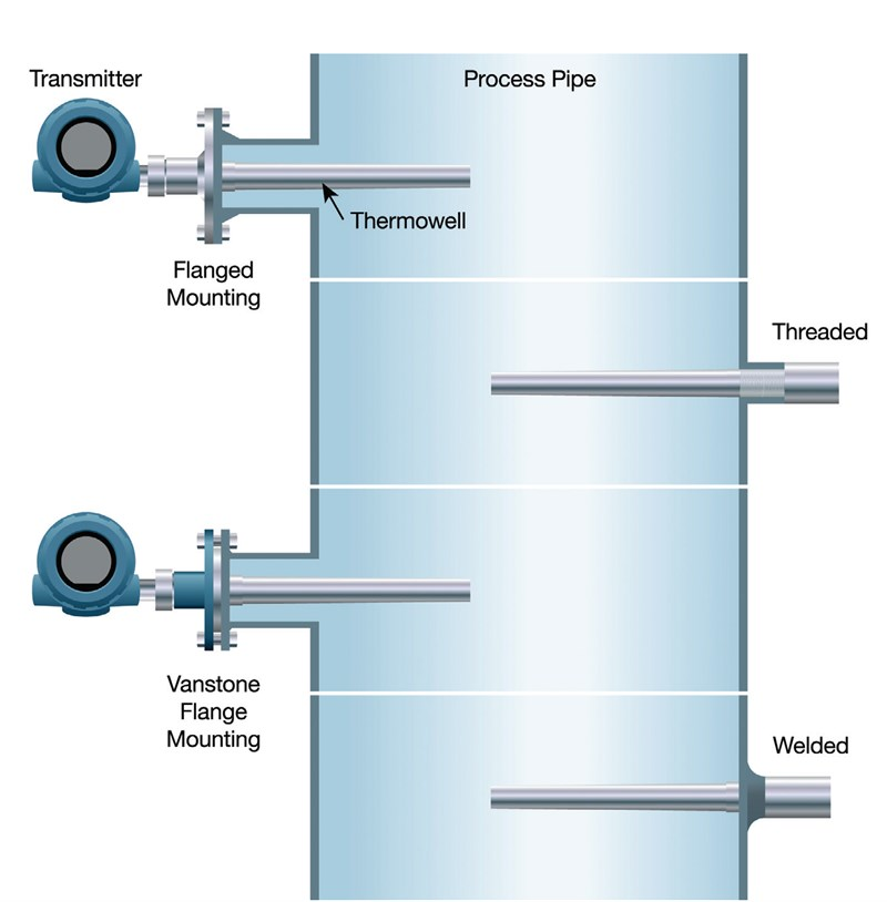
The thermowell installer will select one of four common connection methods to suit the situation:
- Threaded thermowell is connected to the process piping or a vessel, allowing for simple installation and removal. While this is the most popular mounting method, it has the lowest pressure rating and is prone to leaking due to threaded connections.
- Welded thermowell are utilized in applications with high-velocity flow, high temperature, and/or high pressure and are permanently welded to process pipes or vessels. While the thermowell is reliable and leak-proof, it is difficult to remove and requires cutting the thermowell out of the system.
- Flanged thermowell are spud welded to a process pipe or tank, or bolted to a mating flange. They’re utilized in applications that need high fluid velocity, high temperatures, and/or high pressure, as well as corrosive environments.
- Van Stone or lap-joint thermowell are configured between a mating flange and the lap-joint flange. These thermowells allow different materials to be used for the thermowell that comes into contact with the process and the covering flange, which can save money on materials and manufacture.
Challenges of Using a Thermowell
The most difficult issue is fluid flow. A thermowell can have a long service life if it is properly specified and put in a location where the fluid is essentially static, such as in some containers. When a thermowell is immersed in a moving fluid, which is the most common application, problems occur. The thermowell is usually installed perpendicular to the flow, allowing the fluid to hit it from all sides. As a result, it causes a partial obstruction and drags on the fluid.
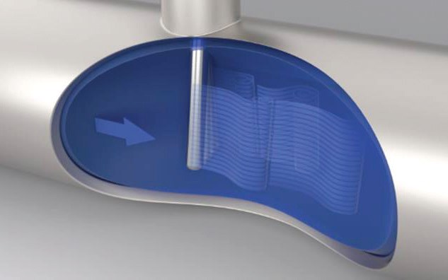
The detachment of vortices from the thermowell is depicted in this model.
High- and low-pressure vortices form on both sides of a spherical thermowell as fluid flows past it. These vortices detach in an alternating pattern, first from one side and then from the other. Vortex shedding is the term for this occurrence. Vortex-induced vibration (VIV) is caused by the differential pressure created by the alternating vortices, which causes strains and transverse and axial displacement, which can eventually lead to fracture. The thermowell appears to be being pulled up and down perpendicular to the flow.
The wake frequency, which is affected by fluid velocity, is the frequency of the oscillations. Because it is not a linear relationship, the vibration does not always increase as the velocity increases. VIV will increase and retreat at various points when fluid velocity changes, therefore, there are conditions where an installation can function relatively safely.
The worst-case situation occurs when the wake frequency matches the thermowell’s inherent frequency, resulting in potentially violent VIV. If the dynamic stresses surpass the thermocouple’s maximum allowed working stress limits, it will wear and fail. Manufacturers should give thermowell calculations that can forecast the likelihood of a thermowell failing. The American Society of Mechanical Engineers (ASME) has a method for estimating the size required for a thermowell to be strong enough to function satisfactorily in a specific application.
In most real-world circumstances, such computations are based on a single set of static process conditions, which is not the case. The traditional method is to construct thermowell as short as the process will allow and as thick as can be inserted, however, this increases the time it takes to capture a temperature change and reduces accuracy. Another option is to discover a profile that can prevent VIV from forming.
Modifying Thermowell Geometry
Because cylindrical, stepped, and tapered thermowell are all essentially circular, they all have similar VIV properties, allowing vortices to form over their entire length. The long vortices are disrupted by a new design that permits them to form on both sides, causing them to balance and cancel each other. As a result, there is considerably less VIV, up to 90% less in some cases.
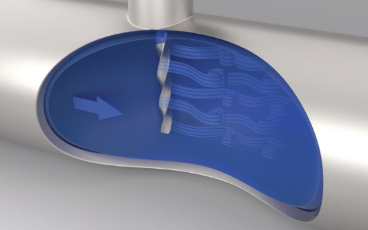
The new and innovative twisted square thermowell lowers mechanical stress by breaking up usual shedding characteristics.
Similar helical geometry has been widely implemented to solve problems with wind turbines and deep-sea risers. It doesn’t need to be put in a precise orientation, and it eliminates the requirement for overly thick thermowell and large diameter process penetrations. It’s also effective and adaptable to a wide range of operational conditions.
Types of Thermowells
The design of the stem is used to classify thermowell. A straight thermowell has the same diameter throughout its entire length of insertion and provides corrosion and erosion protection. Stepped thermowell typically have a 34-inch diameter at the top and a 12-inch diameter near the tip. For sensor devices, the smaller surface area provides for smoother velocities and faster temperature response.
The diameter of the tapered thermowell reduces gradually over the length of the insertion length. They have higher strength and respond quickly to temperature changes. In high-velocity applications, tapered thermowell are most commonly used. Straight thermocouples failed prematurely when exposed to flow-induced vibrations, according to case studies on straight and tapered thermowell used in natural gas pipelines.
Connection Type
Several distinct connection types exist for thermowell to connect to an RTD, thermistor, or thermocouple head. The following are a few of the most common:
- Threaded
- Weld-In
- Socket Weld
- O-Ring
- Flange
Threaded connections are comprised of materials that can be welded or brazed together for greater strength. Weld-in connections are often utilized in procedures where impurities from threads must be avoided, such as in the food and pharmaceutical industries. An O-ring seals inside a sleeve welded to a tank in O-ring connections. The ANSI B16.5 flanged thermowell’s double weld structure seals open joints both internally and externally, preventing corrosive chemicals from entering cracks.
Material Selection
A thermowell’s lifetime is dependent on the material it is made of. When choosing a material, keep in mind the type of chemical, temperature, and flow rate that the thermowell will be subjected to. Chemicals’ corrosive effects are amplified at higher concentrations and temperatures. Erosion can also be caused by particles suspended in fluid. The following is a list of some of the most commonly used materials for thermowell construction:
- Carbon steels
- Chromium/molybdenum steels
- Socket Weld
- Stainless Steel
- Incoloy
- Inconel
- Monel
- Hastelloy
- Haynes Alloy
- Titanium
Carbon steels have a low resistance to corrosive chemicals and are only suitable for low-temperature and low-pressure applications. Stainless steel is the most frequent material for thermowell. A stainless steel thermowell is inexpensive and it is heat and corrosion resistant. High-strength stainless steel containing chromium and molybdenum is utilized in pressure vessels. The use of molybdenum improves corrosion resistance. Cobalt, nickel, chromium, and tungsten make up Haynes alloy. Sulphidizing, carburizing, and chlorine-containing conditions are the most common applications.
Insertion Length
The insertion length is the distance between the thermowell’s connection point and the tip. The insertion length should be long enough to allow the full temperature-sensitive section of the measurement instrument to extend into the medium being measured for the best accuracy. When using a temperature sensor to measure the temperature of liquids, the device should be extended into the solution for at least one inch longer than the temperature-sensitive section.
It should be immersed in gas or air for the length of the temperature-sensitive section plus three inches higher. A thermocouple or thermistor’s temperature-sensitive region is short, so a thermowell with a shorter insertion length can be utilized. For acceptable accuracy, the temperature-sensitive part of RTDs, bimetal thermometers, and liquid in glass thermometers should be immersed at least 212″ in liquid.
Conclusion
Exposure to flow, heat, and pressure causes all temperature sensor equipment to deteriorate. The severe processing environment can have an impact on the sensor’s performance as well as its structural integrity over time. Metals applied in the production of thermocouple probes, for example, are susceptible to corrosive conditions. Furthermore, the thermocouple wire is typically 0.10 to 0.20″ in diameter and will experience metallurgical changes when exposed to heat for an extended time.
To reduce measurement drift, thermowell insulates the measuring sensor from the detrimental effects of the process environment. All temperature data for important processes should be recorded using temperature controllers or other recording devices. Temperature sensors used in such operations should also be calibrated regularly to ensure accuracy.
For thermistors, thermocouples, and RTD probes, dry block probe calibrators provide NIST traceable calibration. Non-contact devices such as thermal cameras and pyrometers, as well as infrared blackbody calibrators, have a repeatability of 1%. While calibrations can be done in-house, using a certified AS17025 calibration facility ensures that the procedures are NIST traceable.
Buy Equipment or Ask for a Service
By using Linquip RFQ Service, you can expect to receive quotations from various suppliers across multiple industries and regions.
Click Here to Request a Quotation From Suppliers and Service Providers
Read More In Linquip
- 4 Types of Thermowell: Application and Duty
- Thermocouple vs. Thermopile: A Complete Comparison & Advantages of Each Type
- The Best USA Thermocouple Manufacturers in 2022
- Working Principle of Thermocouple: 2022 Guide + Diagram
- Difference Between Thermopile and Thermocouple
- Difference Between Thermistor and Thermostat: Which One Outperforms the Other?
- Types of Thermometers: All You Need to Know
- A Good Look at Types of Thermostats
- Thermistor vs Thermocouple: Complete Comparison & Practical Selection Guide
- Thermocouple for Water Heater: How does it Work?
- Thermocouple Types: A Complete Comparison Between Them
- What is a Thermocouple & How Does It Work?

