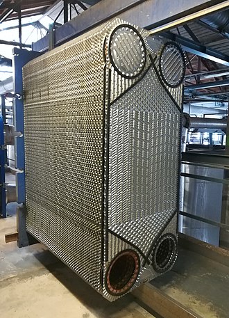
The working principle of a plate heat exchanger is determined by its construction, function, and application. A plate heat exchanger is a class of heat exchangers for transferring heat between two fluids using metal plates. The plate heat exchanger has a notable advantage over conventional heat exchangers because the fluids are exposed to a much broader surface area as the fluids are spread over the plates. This facilitates heat transfer and considerably increases the rate of the temperature change.
Today, plate heat exchangers are common, and very tiny brazed ones are applied in the hot-water parts of millions of combination boilers. The high efficiency of such small dimensions leads to an increase in the Domestic Hot Water (DHW) flow rate of combination boilers. The small plate heat exchanger has a great influence on domestic heating and hot water supply. Larger commercial plate heat exchangers employ gaskets between the plates, while smaller ones can be brazed.
The plate heat exchanger (PHE) was first invented in 1923 by Dr. Richard Seligman and revolutionized the systems of indirect cooling and heating of fluids.
The concept of a heat exchanger is to use pipes or other containment vessels to cool or heat one fluid by transferring heat between it and another one. In most cases, the heat exchanger consists of a coiled tube containing one fluid passing through a chamber holding another fluid. The tube walls are typically made of metal, or another material with high thermal conductivity, to help the interchange mechanism, while the outer casing of the larger enclosure is built of plastic or coated with thermal insulation to prevent heat leakage from the exchanger.
Plate Heat Exchanger Basics
In this section, we describe the working principles of a plate heat exchanger in detail under the headings of structure, configuration, flow distribution, and heat transfer.
Plate Heat exchanger Structure
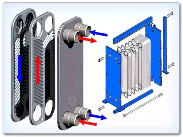
A plate heat exchanger comprises a series of parallel plates placed one above the other to form a series of channels for the flow of fluids between them. The space between two neighboring plates forms the channel through which the fluid flows. The inlet and outlet holes at the plate corners let hot and cold fluids flow through alternating channels in the
exchanger, causing a plate to always be in contact with the hot fluid on one side and the other with the cold.
The size of a plate can be from a few square centimeters (100 mm by 300 mm) to 2 or 3 square meters (1000 mm by 2500 mm). The number of plates in an individual exchanger varies from ten to several hundred, which makes surface exchange areas reach up to thousands of square meters.
The following figure shows the flow through a plate heat exchanger. As seen in the figure, the fluid is divided into several parallel flows to make a perfect counter flow.
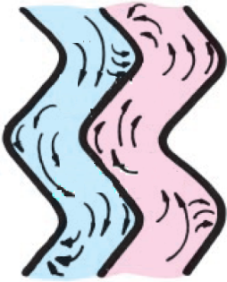
In general, these plates are corrugated to increase the turbulence, the thermal exchange surface, heat exchanger rate and improve the exchanger mechanical rigidity. Corrugation is obtained by cold forging of sheet metal with thicknesses ranging from 0.3 mm to 1 mm.
The most commonly utilized materials for the plates are stainless steel (AISI 304, 316), titanium, and aluminum.
Plate Heat exchanger Configuration
The corrugation on the plates drives the fluid on a tortuous path, creating a distance from 1 to 5 millimeters between two adjacent plates.
The fluids can pass through the channels in series (a less common solution) or parallel by making counter-flow configurations.
Serial configuration is used for low flow rates but high heat jump cases; the biggest problem is high-pressure drop and incomplete counter flow.
Parallel configuration with countercurrent channels is utilized for high flow rates with a mediocre temperature drop and is the most broadly used configuration.
When there is a large difference between the flow rates (or the maximum allowable pressure drop) of two fluids, the exchanger can operate twice with the lower flow fluid (or higher losses) to balance the pressure drop values or the channels specific flow rates.
One of the most typical problems with plate heat exchangers is the irregular supply of all channels in parallel. The fluid tends to be distributed more in the first channels than the last channels to balance the pressure drop.
As the plates number increases, even the distribution decreases. So, the overall performance of the exchanger is reduced.
Plate heat exchanger plates can generate vertical or diagonal flows, depending on the gaskets arrangement. For vertical flows, the inlet and outlet of a particular flow are placed on the same side of the heat exchanger, while for diagonal flows, they are located on opposite sides.
Assembly of the plate package includes alternating between the “A” and “B” plate configurations for the respective flows. Installing the plate package in the vertical flow mode requires a suitable gasket arrangement because the A and B configurations are equivalent (they are rotated by 180°, as seen in the following figure, part a). This is not feasible with diagonal flows, which need both mounting plate types.
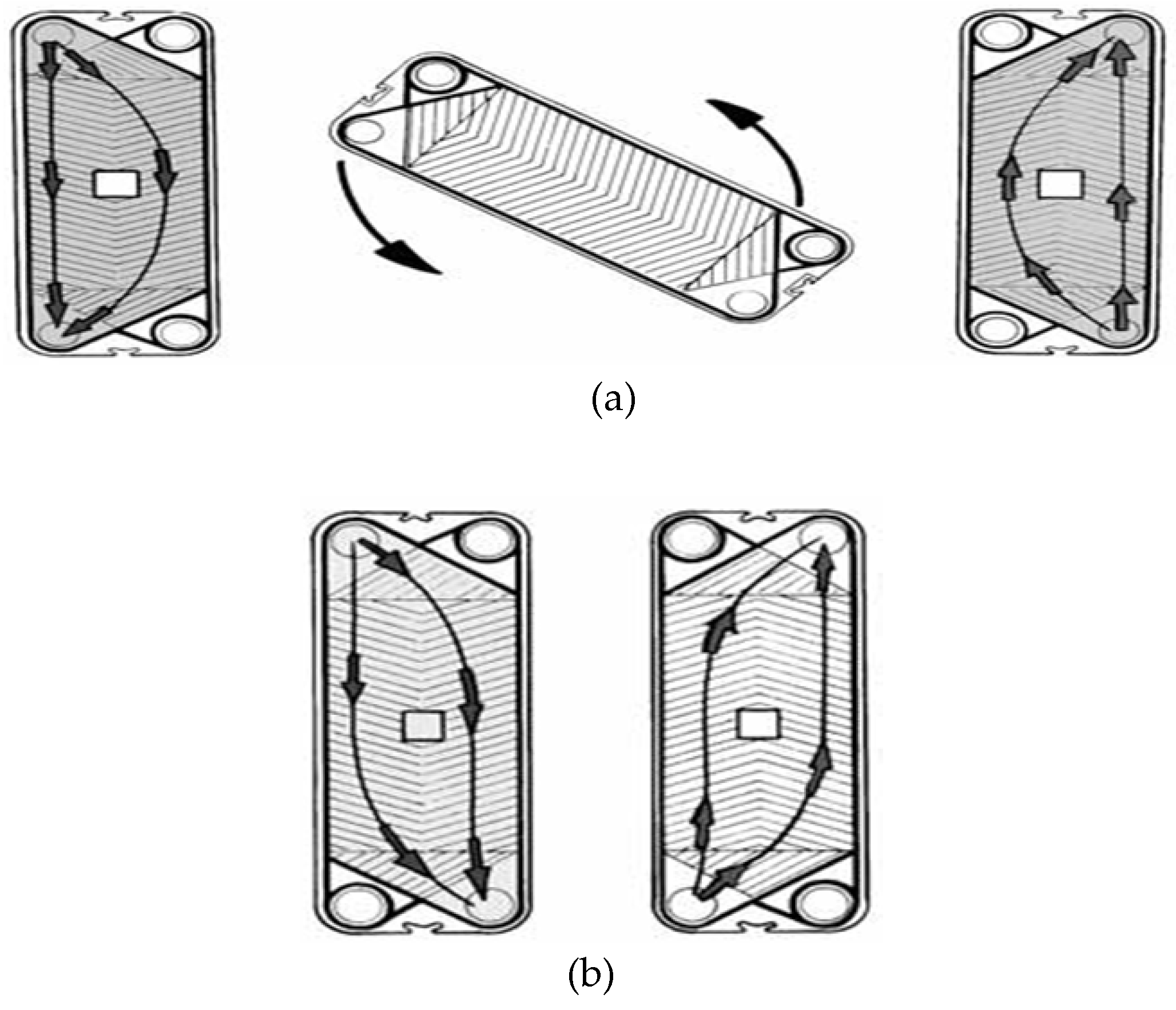
Plate Heat exchanger Flow Distribution
The simplest type of plate heat exchanger arrangement is that in which both fluids have only one passage, so no change occurs in the direction of the fluid flows. This type is known as a 1-1 single-pass arrangement and is divided into two subsets: counter flow and parallel flow.
A notable advantage of the single-pass arrangement is that the inlets and outlets of the fluids can be mounted on the fixed plate, which makes it easy to maintain and clean the equipment without interrupting the work of the pipe. This design is known as the U-arrangement and is the most common single-pass design. Another single-pass design is Z-arrangement, in which there are fluids inlets and outlets through both endplates.
U and Z-arrangements of a single pass plate heat exchanger are shown in the following figure.

Counter flow, where the currents flow in the opposite directions, is usually preferred over parallel flow where the currents flow in the same direction due to higher achievable thermal efficiency.
Multi-pass arrangements can also be used to increase the heat transfer or fluids flow velocity. These arrangements are usually required in cases there is a significant difference between the flow rates of the currents.
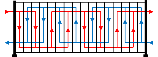
Plate Heat exchanger Heat Transfer
The total heat transfer rate between the fluids passing through a plate heat exchanger can be expressed by the following equation:
Q=UA\Delta T_{m}
where U, A, and ∆Tm are the overall heat transfer coefficient, total plate area, and the effective mean temperature difference respectively. The total plate area can be calculated as follows:
A=N_pA_p
Np and Ap are the number of plates (except the end plates) and the area of each plate. Also, the overall heat transfer coefficient is expressed as:
U=\frac{1}{\frac{1}{h_{hot}}+\frac{1}{h_{cold}}+\frac{t_P}{k_p}+R_{f,hot}+R_{f,cold}}
where hhot and hcold are convective heat transfer coefficients of hot and cold fluids, respectively. tp and kp are plate thickness and conductivity of plates, respectively. Finally, Rf, hot and Rf, cold are fouling factors of hot and cold fluids.
There are two basic methods used to calculate the heat transfer in a plate heat exchanger: the log-mean temperature difference (LMTD) and the thermal effectiveness. In the first approach, the heat transfer rate is given by the following equation:
Q=UA(F\mathit{\Delta}T_{lm})
ΔTlm is the log mean temperature difference, expressed by the next equation, and F is the correction factor, a function of heat exchanger configurations.
\mathit{\Delta}T_{lm}=\frac{\mathit{\Delta}T_1-\mathit{\Delta}T_2}{{{ln}}ln\ \frac{\mathit{\Delta}T_1}{\mathit{\Delta}T_2}\ }
The temperature differences in the above equation are given for the parallel flow heat exchanger as follows:
\mathit{\Delta}T_1=T_{hot,\ in}-T_{cold,\ in}
\mathit{\Delta}T_1=T_{hot,\ out}-T_{cold,\ out}
And for counter flow heat exchanger:
\mathit{\Delta}T_1=T_{hot,\ in}-T_{cold,\ out}
\mathit{\Delta}T_1=T_{hot,\ out}-T_{cold,\ in}
The second approach is based on the definition of heat exchanger effectiveness as the ratio of the actual heat transfer to the maximum theoretical heat transfer:
\varepsilon =\frac{Q}{Q_{max}}
Q_{max}={\left(\dot{m}c_p\right)}_{min}{\mathit{\Delta}T}_{max}
The actual heat transfer is driven using an energy balance as:
Q={\left(\dot{m}c_p\right)}_{hot}(T_{hot,in}-T_{hot,out})
Q={\left(\dot{m}c_p\right)}_{cold}(T_{cold,out}-T_{cold,in})
To know more about the effectiveness of a heat exchanger, visit this link.
Plate Heat Exchanger Types
There are two main types of plate heat exchangers, including Brazed Plate Heat Exchangers (BPHE) and Plate and Frame Heat Exchangers.
Plate and Frame Heat Exchangers
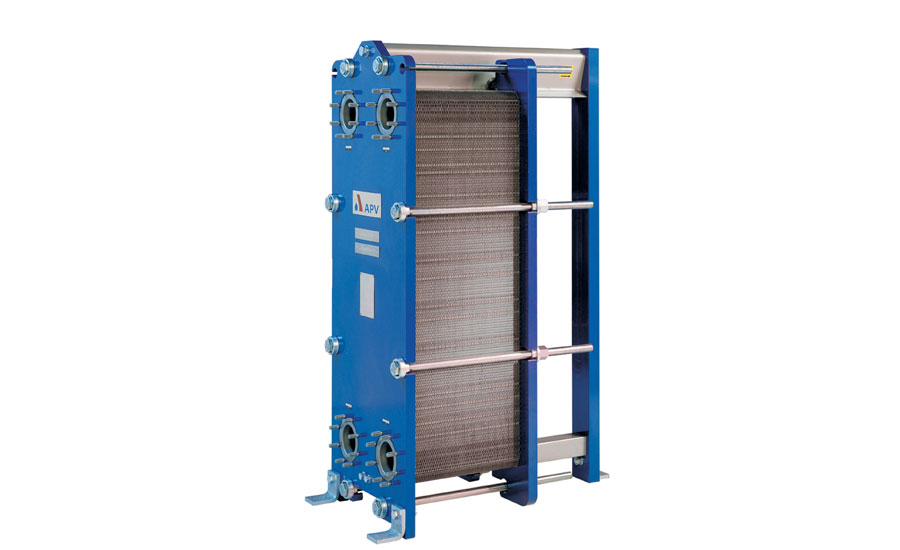
The plates form a frame in which the plates are pressed with headers and tie rods in the plate heat exchanger, and gaskets support the seal. In addition to their sealing effect, the gasket works to direct the flow of the fluids and is placed along the grooves at the edges of the plates.
The maximum temperature used to seal heat exchangers is between 80 and 200°C, while the pressure can be raised up to 25 bars. Gaskets exist in different types of butyl or silicone rubber.
The main features of this type of heat exchanger are as follows:
- Quick and easy disassembly to clean the parts and control operations.
- Compatibility with variable working conditions by adding or eliminating heat plates to change the installed thermal flow.
- Prevention of contamination of other fluid due to any liquid leakage resulted from incomplete sealing of the washers and directing it away.
- The limitation for the maximum pressure and temperature values due to the gaskets operation.
- The possibility of using materials poorly adapted to soldering, like titanium.
- High costs due to the moulds design, presses, and all the stages of construction.
- High cost of gaskets.
Brazed Plate Heat Exchangers
Brazed plate heat exchangers do not have a header, tie bars, or gaskets because the plates are furnaces brazed at 1100°C. During the assembly phase, the brazing material sheet (typically copper but also nickel) is placed between the plates, pressed tightly, and then baked for some hours. The BPHE exchanger is more compact and lighter than the exchanger with gaskets.
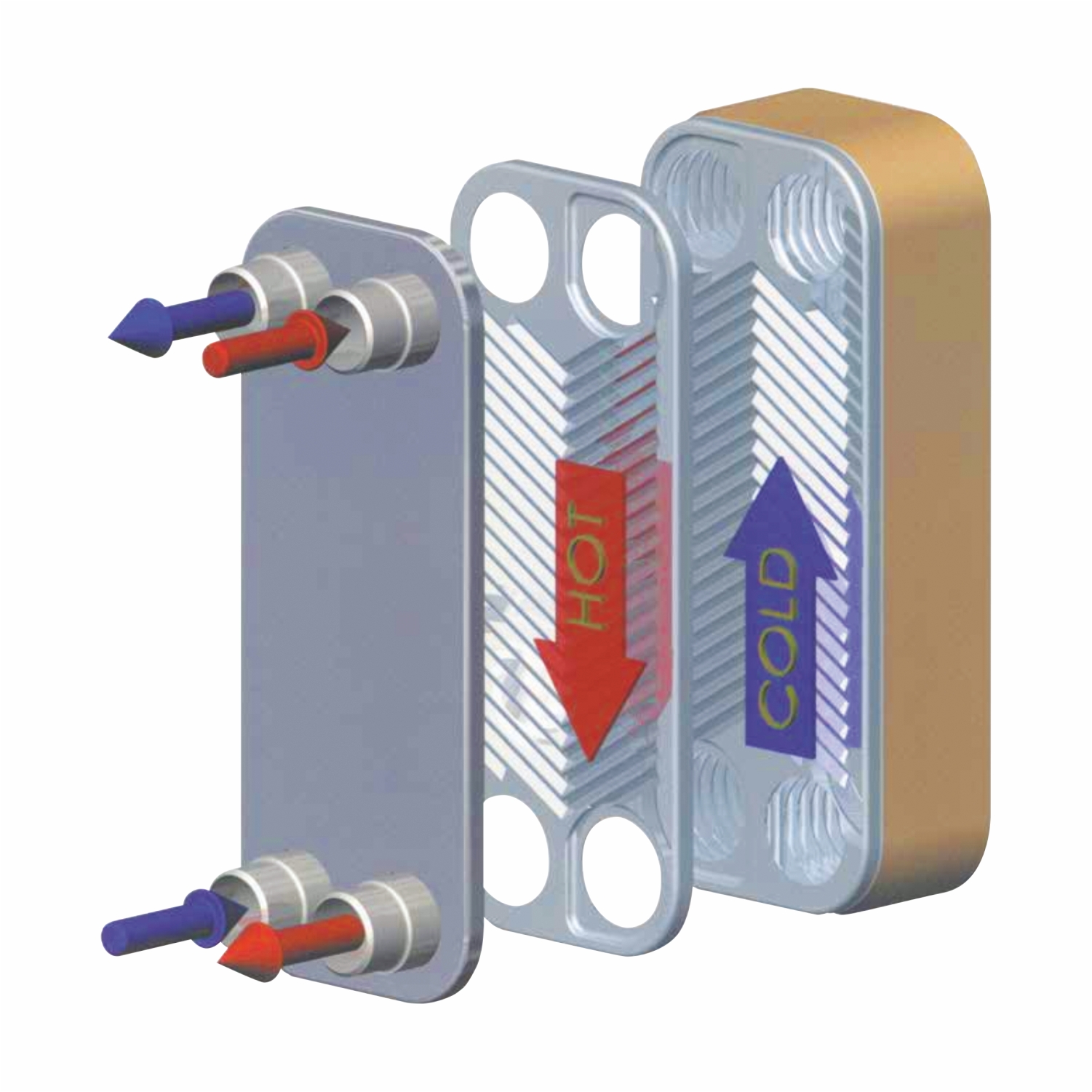
The crossing points between the two coupled plates corrugations create a dense network of contact points that provide pressure tightness and cause swirling streams enhancing the heat exchange. In this way, there is high turbulence of the fluids even at low input velocities, and the flow reaches from laminar to turbulent in low flow rates.
It is instantly realized that the path created by the fluids is chaotic. In fact, the cross-section is constantly changing. The main drawback of these exchangers is that they are not removable. Therefore maintenance and cleaning are not practicable or at least are challenging, and there is no flexibility because the number of plates cannot be changed at all. The surface of the plates is corrugated to increase the fluid turbulence through the channels.
Plate Heat Exchanger Evaluation
All plate heat exchangers appear to be the same from the perspective of the outside. There are differences inside them in the plate design details and the sealing technologies applied. Hence, when assessing a plate heat exchanger, it is essential to study the details of the products and analyze the stages of research and development conducted by the manufacturer, after-sales service, and availability of spare parts.
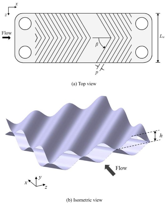
An important feature to consider when evaluating a heat exchanger is the corrugated shape of the heat exchanger. There are two types of corrugations: intermating and chevron. In general, greater enhancement in heat transfer through the chevrons is produced due to an increase in pressure drop. So, they are more used than intermating corrugations.
There are many modifications methods to increase the efficiency of heat exchangers, each of which is extremely doubtful to be supported by a commercial simulator. Moreover, some exclusive data may never be released from the heat transfer enhancement manufacturers. But, this does not mean that none of the pre-measurements of emerging technology have been performed by the engineers.
The primary purpose of having a cost-benefit heat exchanger rather than using a traditional heat exchanger must be achieved by heat exchanger improvement. Fouling capability, reliability, and safety are other factors that need to be addressed.
Periodic cleaning or on-site cleaning is the most efficient way to flush out waste and dirt, which reduces the heat exchanger efficiency over time. This method requires draining both sides of the plate heat exchanger and then isolating it from the fluid in the system. Water should be flushed out on both sides to make it completely clear. The flushing should be done regularly in the opposite direction for the best effects.
When done, it is then time to apply a circular pump and a solution tank to transfer the cleaning agent while ensuring that it is compatible with the gaskets and plates of the plate heat exchanger. Finally, the system must be flushed with water again to make the discharge stream clear.
Plate Heat Exchanger Advantages and Disadvantages
In this section, we will mention some strengths and drawbacks of plate heat exchangers compared to the shell and tube heat exchangers.
Advantages
- Simple disassembly and various plate configurations provide the flexibility to the plate heat exchangers to be compatible with new process applications by simply adding or removing, or rearranging the plates.
- The narrow channels between adjacent plates allow a small volume of fluid contained in the plate heat exchanger. Therefore, the device has a rapid response to changes with short lag times so that the temperatures are readily controlled.
- Plate heat exchanger production is almost inexpensive.
- Compared to only 50% heat recovery of shell and tube heat exchangers, up to 90% of the heat is recovered in plate heat exchangers due to the plate corrugations and the small hydraulic diameter causing enhanced turbulence and high rates of heat transfer.
- For the same heat transfer area, plate heat exchangers often occupy 80% less space than the shell and tube heat exchangers.
Disadvantages
- An important weakness of plate heat exchangers is due to the standard plate gaskets, which cannot tolerate pressures exceeding 25 ATM and temperatures more than 160 °C causing leakage.
- The corrugated configuration of plates and the small flow spaces cause high-pressure drop due to friction, which raises pumping costs.
- Friction between the plates can induce wear and, consequently, the formation of small holes that are challenging to locate.
- Although sometimes plate heat exchangers can be used in condensation or evaporation processes, it is not recommended for gases and vapors due to space limitations within the channels and the pressure constraints.
- Another limitation is the use of the plate heat exchangers in the processing of highly viscous fluids or those containing fibrous material because of the associated high-pressure drop and the flow distribution problems.
Read More In Linquip
- 16 Parts of Heat Pump and Functions (Clear Guide)
- 3 Types of Heat Pump + Working Principle ( Clear Guide)
- Heat Exchanger vs. Chiller: Which One is the Best for You?
- Difference Between Heat Exchanger and Condenser: A thorough guide 2022
- Heat Exchanger Efficiency Calculation & Equation
- Demystifying Heat Exchanger Sizing: A Comprehensive Guide
- Tubular Heat Exchangers: Usage & Working Principle
- What is Coil Heat Exchanger? Design Example
- Heat Pump Efficiency: Equation & Formula
- How Does a Heat Pump Work?
- Advanced Guide: What Is Tube In Tube Heat Exchangers
- What is Plate Heat Exchanger?
- What is Scraped Surface Heat Exchanger? Find it Where it is used
- Types of Plate Heat Exchanger: Different Types with Wide Use
- What is u-tube heat exchanger? An undeniable advantageous system
- Types of Shell and Tube Heat Exchanger
- What are Counter Flow Heat Exchangers and its Working Principles?
- The Complete Guide To Air Source Heat Pumps Disadvantages
- What are Double Pipe Heat Exchangers and Their Working Principles?
- Heat Exchanger Parts: Description of Configuration
- What is Cross Flow Heat Exchangers and its Working Principles
- Installing an Air Source Heat Pump: Everything You Need to Know
- How to Calculate the Efficiency of Heat Exchangers?
- What Are Air Source Heat Pumps? A Complete Guide
- What is the Difference between Heat and Temperature?
- What Are Air Source Heat Pumps? A Complete Guide
- Heat Exchanger Design: How Is a Heat Exchanger Designed?
- Types of Heat Exchangers: An Introduction to All Essential about Specifications
- Best Mini Split Heat Pump for Cold Weather in 2022 {Ultimate Guide}
- A General Overview of Heat Pump Problems
- At What Temperature is a Heat Pump Not Effective? Easy Answer
- Heat Pumps vs Air Conditioners: The Everlasting Battle

