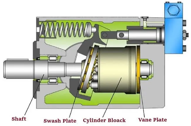
Working Principles of Hydraulic Pump – The functioning concept of hydraulic pumps is similar to that of displacement pumps. A hydraulic pump is a key component of a hydraulic system because it converts mechanical energy from an engine or motor to hydraulic energy. To conduct beneficial work, the hydraulic pump comprises pressure and flow.
The flow of a pump is determined by its speed and displacement (volume). By rotating a pump faster, a bigger pump may transfer more fluid at once or push on more fluid. In hydraulics, power is a combination of pressure and flow. The horsepower is doubled by doubling the pressure while keeping the flow the same. On the other side, doubling the flow while maintaining the same pressure doubles the horsepower.
⇒ View a List of Hydraulic Pump for Sale and Their Suppliers ⇐
What is a Hydraulic Pump
The core of a hydraulic system is a hydraulic pump, which is a mechanical source of power that transfers mechanical energy into hydraulic energy (i.e. flow, pressure). In other words, it produces enough flow to counteract the pressure generated by the load at the pump output. Hydraulic power is pressure times flow, whereas mechanical rotational power is the combination of torque and speed.
When a hydraulic pump is turned on, it causes a vacuum at the pump inlet, which draws liquid from the reservoir into the pump’s intake line, where it is supplied to the pump output and pushed into the hydraulic system by mechanical action.
Positive-displacement and non-positive-displacement pumps are the two types of pumps. Hydrostatic pumps are positive displacement pumps, whereas hydrodynamic pumps can be fixed displacement pumps (flow through the pump per rotation of the pump) or variable displacement pumps (flow through the pump per rotation of the pump) with a more complicated construction that enables the displacement to be adjusted. In everyday life, hydrodynamic pumps are more common. Pascal’s law governs the operation of all sorts of hydrostatic pumps. Positive-displacement hydraulic pumps are the most common type of hydraulic pump utilized in hydraulic systems.
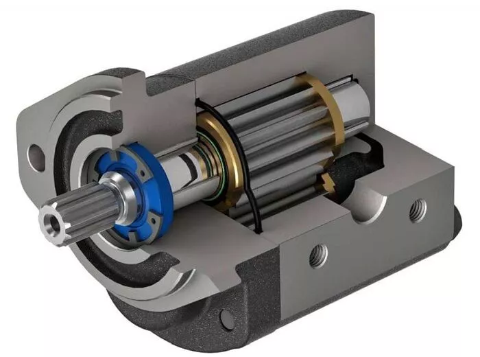
In a cycle, positive displacement pumps supply a consistent amount of fluid. These pumps have a set discharge quantity each revolution and create fluid flow proportionate to their displacement and rotor speed. In most industrial fluid power applications, these pumps are employed. The output fluid flow remains constant regardless of system pressure (load).
The main benefit of these pumps is that the high- and low-pressure portions (i.e., the input and output regions) are separated, preventing the fluid from leaking back owing to increased pressure at the outputs. Because of these characteristics, the positive displacement pump is the most suitable and widely recognized pump for hydraulic systems. Positive displacement pumps have several benefits over nonpositive displacement pumps, including the capacity to create high pressures, good volumetric efficiency, and high power to weight ratio. Positive displacement pumps have a modest change in efficiency over the pressure range, and their working range of pressure and speed is much greater.
Working Principle of Hydraulic Pumps
For each rotating cycle of the pumping component, the same amount of liquid is displaced or delivered in a positive-displacement pump. The precise tolerance fit between the pumping component and the pump housing allows for consistent delivery throughout each cycle. In a positive-displacement pump, this indicates that the amount of liquid sliding past the pumping element is minimal and inconsequential in comparison to the maximum potential delivery.
As a result, regardless of the pressure variations against which the pump operates, the delivery in each cycle remains essentially constant. If there are a lot of fluid slippages, the pump will stop working and will need to be fixed or replaced.
Pumps that use positive displacement might have a fixed or variable displacement. At a certain pump speed, the output of a fixed displacement pump remains constant during each pumping cycle. A variable displacement pump’s output, on the other hand, may be changed by altering the displacement chamber shape.
Positive displacement pumps are known as hydrostatic pumps, whereas non-positive displacement pumps are known as hydrodynamic pumps. The term “hydrostatic” refers to a pump that converts mechanical energy to hydraulic energy with a minimal volume and velocity of the liquid. The velocity of the liquid and its movement are high in a hydrodynamic pump, and the output pressure is proportional to the velocity of the liquid flow. Positive displacement principles are used in the majority of hydraulic pumps.
A hydraulic pump’s hydraulic and mechanical efficiency can be defined as follows:
\eta _{hydraulic}=\frac{Q_{actual}}{Q_{Theoretical}}\times100
\eta _{mechanical}=\frac{T_{Theoretical}}{T_{actual}}\times100
Q is flow rate output and T is torque to drive in the above equations.
Types of Hydraulic Pumps
Positive Displacement Pumps
A positive displacement pump moves liquid by trapping a specific amount and pushing it into the discharge pipe (displacing it).
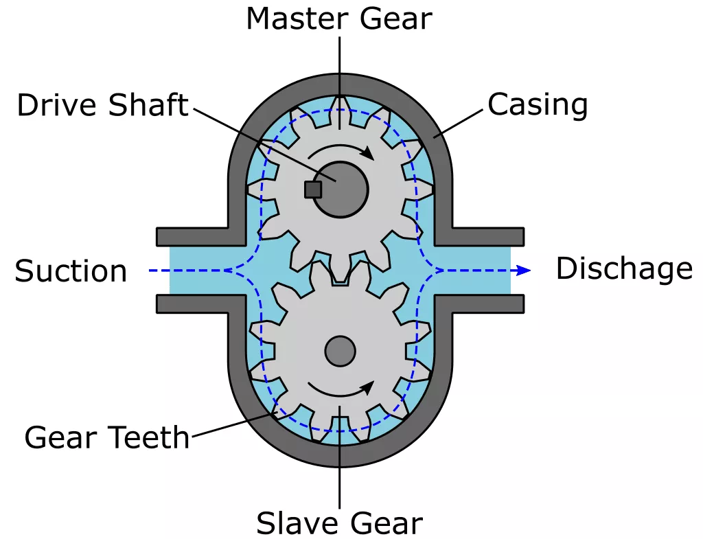
An expansion cavity is used on the suction side of some positive displacement pumps, while on the discharge side, a contraction cavity is used. Liquid flows into the pump when the cavity grows on the suction side, and liquid flows out of the discharge when the cavity contracts. Each operation cycle maintains a consistent volume.
Positive displacement pumps, unlike centrifugal pumps, may theoretically provide the same flow at a fixed speed (rpm) regardless of discharge pressure. Positive displacement pumps are hence known as constant flow devices. When the pressure is increased, there is a minor rise in internal leakage. As a result of the leakage, a truly constant flow rate is not possible.
Because positive displacement pumps do not have a shutdown head like centrifugal pumps, they cannot function against a closed valve on the pump discharge side. Running against a closed discharge continues to create flow, raising the pressure in the discharge line until the line explodes, the pump is severely damaged, or both. As a result, a relief or safety valve is required on the positive displacement pump’s outlet side.
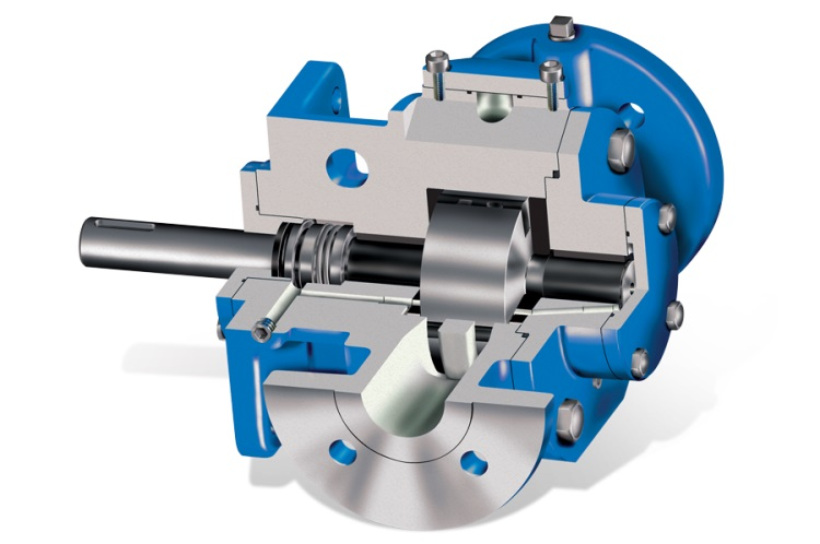
The relief valve can be mounted on the inside or outside the building. Internal relief or safety valves are often provided by the pump manufacturer. An internal valve is often used only as a safety measure. External relief valves with a return connection to the suction line or supply tank, on the other hand, improve both human and equipment safety.
Gear Pumps
Positive displacement (or fixed displacement) gear pumps (with exterior teeth) have a simple functioning and inexpensive construction. Hydraulic gear pumps have a displacement capacity ranging from 1 to 200 milliliters. Compared to gear pumps, vane pumps, and piston pumps, they have a lower volumetric efficiency. The fluid is pushed around the gears to provide pressure to the output side of these pumps, which generates pressure by meshing the gear teeth.
Although some gear pumps are significantly noisy than others, contemporary versions are far more dependable and quieter than previous kinds. Split gears, helical gear teeth, and higher-quality tooth forms that mesh and unmesh more smoothly all contribute to this. These elements help to lessen the pressure ripple and the problems that come with it.
Because the gears continually wear down the housing and major bushings, the gear pump has a lower risk of serious failure than most other hydraulic pump designs. It reduces the pump’s volumetric efficiency until it becomes utterly unusable. The device will frequently cease operating or break down as a result of this.
Rotary Vane Pumps
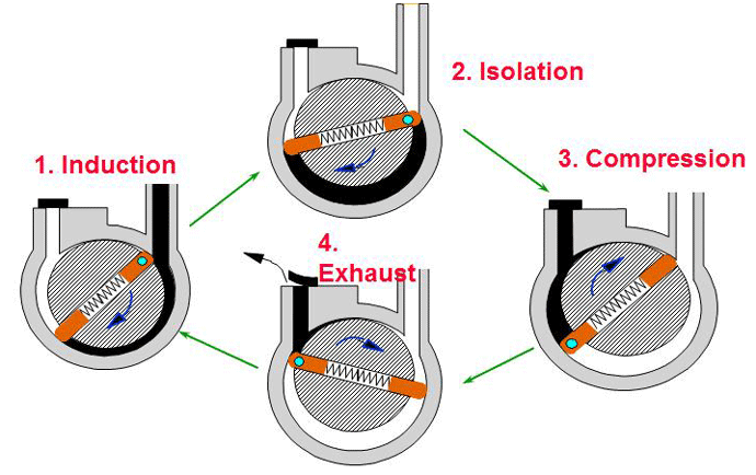
The way the vanes come into contact with the pump housing is an important feature of these positive displacement pumps, and the vane tips are machined at this point. The major goal of the “lip” designs is to create a tight seal between the inner surface of the housing and the vane while reducing wear and metal-to-metal contact. Spring-loaded vanes pull the vane out of the center of rotation toward the pump housing, or vanes were loaded hydrodynamically through a pressured system fluid in previous efforts.
Screwdriver Pumps
Screw pumps are positive displacement pumps made out of two Archimedes screws that are intermeshed and housed in the same chamber. These pumps are used to deliver high flow rates at low pressures of up to 100 bars. They’ve been utilized on ships with a constant pressure hydraulic system installed throughout the vessel, mostly to operate ball valves but also to drive steering gear and other systems. The screw pumps have the advantage of being quiet. Screw pumps, on the other hand, have low efficiency.
The fundamental issue with screw pumps is that the hydraulic response force is transmitted in the opposite direction of the flow.
To get around this problem, there are two options:
- A thrust bearing should be placed beneath each rotor;
- A hydraulic balance should be achieved by sending a hydraulic force to a piston beneath the rotor.
Types of screw pumps include:
- Single-end
- Double-end
- Single rotor
- Multi rotor timed
- Multi rotor untimed.
Piston Pumps
The high-pressure seal reciprocates with the piston of a piston pump, which is a positive displacement pump. Pumps with pistons are used to move liquids or compress gasses. They may work in a variety of conditions. High-pressure operation is possible without affecting the flow rate much. When dealing with viscous fluids, piston pumps are capable of handling solid particles.
A piston pump uses an oscillation mechanism in which the down-strokes create pressure differentials, filling the pump chambers, and the up-stroke pushes the fluid out for use. These pumps are typically used in applications that need high, steady pressure, such as water irrigation or delivery systems.
Lift pumps and force pumps are the two types of piston pumps. Both can be operated by hand or with the help of an engine.
Lift Pump
The lift pump’s piston sucks liquid into the bottom half of the cylinder through a valve as it rises. The liquid enters the top portion of the cylinder through valves fitted in the piston during the downstroke. The liquid is discharged from the upper half of the cylinder through a spout on the following upstroke. The height of water sustained by air pressure against a vacuum is the limit of lift pumps.
Force Pump
The force pump’s piston sucks liquid into the cylinder through an intake valve as it rises. The liquid is released into the output pipe by an outlet valve on the downstroke.
Variable Displacement Pump
The displacement or volume of the pumped liquid per revolution of the pump shaft may be adjusted while the pump is running with a variable displacement pump.
Pumps that may act as a hydraulic motor and convert fluid energy into mechanical energy are known as reversible variable displacement pumps.
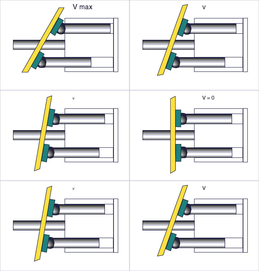
Because the normal vector to the swashplate is parallel to the rotation axis in a variable displacement pump, the pistons in their cylinders do not move, and so there is no output. The swashplate moves up and down, controlling the pump’s output from zero to maximum. Direct displacement control pumps and servo control pumps are two forms of variable displacement axial piston pumps.
A direct displacement control pump is an axial piston pump with direct displacement control that is controlled by a mechanical lever attached to the axial piston pump’s swashplate. Higher system pressures need more force to move the lever. Direct displacement control is therefore only suitable for light or medium-duty pumps. Heavy-duty pumps, on the other hand, require servo control.
Instead of a shaft connecting the pump to an external motor, a direct displacement control pump uses links and springs and occasionally magnets. This reduces the amount of moving components. Furthermore, the components are shielded and lubricated, and the resistance to liquid flow is decreased.
Axial Piston Pumps
The axial piston pump is the most common variable displacement pump used in automobile systems. Several pistons are housed in cylinders that are parallel to one another and spin around a central shaft in these pumps. At one end of the pistons, a swashplate is connected. The angle of the plate pushes the pistons in and out of the cylinders as they spin. A rotary valve connects each cylinder to the liquid supply and delivery lines on the opposite end of the swashplate.
The stroke of the piston may be varied continuously by changing the angle of the swashplate. There will be no liquid flow if the swashplate is perpendicular to the rotating axis. If the swashplate is at a severe angle, however, a huge amount of liquid will be pumped. Some pumps allow the swashplate to move in both directions from zero, pushing the liquid in both directions without reversing the pump rotation.
The bent axis pump is a good example. The side stresses on the pistons are reduced by the bent axis.
A piston pump may be turned into a variable displacement pump by adding springs in line with the piston. As back-pressure rises, the displacement is not positively controlled, instead, it decreases.
Hydraulic Pump Maintenance
The working conditions of the different hydraulic components influence the necessity for hydraulic preventative maintenance throughout time. For piston pumps, for example, a service period of 10,000 hours (about 14 months) is commonly suggested. A list of daily maintenance duties is provided below.
- Inspect the oil levels in the power unit’s tanks.
- Inspect the oil for temperature fluctuations.
- Check for water or dirt in the oil in the system.
- Look for any leaks.
- Screws and pipe clamps should be checked and tightened.
- Check the values on the pressure gauge.
- To detect changes, listen to the operating noise of the hydraulic oil pump and electric motors.
- All drip pans on the valve panel should be empty.
- Wipe an item clean before analyzing it for probable leaks in valve groups.
- Pipes, components, and tanks should all have clean surfaces.
- Consult the operators to see whether any servicing or maintenance is necessary.
- Check the service book to check if any issues have been noted by the operators.

Conclusion
Hydraulic pumps are frequently mentioned in today’s environment. Certain projects would be nearly difficult to execute or build without a hydraulic pump and its components. With tremendous accuracy and control, these small pieces can press large items into place. Assembly machinery, construction machines, and farming equipment all require hydraulic pumps. Any hydraulic system’s heart is the hydraulic pump. The question “How does a hydraulic pump work?” was answered in this article. You are encouraged to visit the Hydraulic Pump For Sale in Linquip website to find suitable devices based on your application.
FAQs about Hydraulic Pumps
1. What Is Hydraulics and How Does It Work?
A hydraulic system is made up of several parts. A reservoir, pump, fluid, valves, motor, hose, cylinder, and filter are all included. Before the pressurization procedure, the fluid is held in the reservoir. Hydraulic oil is usually used as the fluid, and it is the lifeblood of the entire system. To eliminate any impurities, the oil passes through a filter.
2. Is a Hydraulic Pump Capable of Producing Pressure?
Engineers dispute the issue of hydraulic pump pressure from time to time. Is it true that hydraulic pumps generate pressure? When a pump creates a flow of fluid, it creates pressure when the fluid encounters any type of resistance.
The pressure will not be there if the hydraulic pump is not connected to a system since nothing will oppose the flow of fluid. Many engineers feel the pumps do not genuinely produce pressure because of the absence of pressure. However, not all specialists are in agreement.
Some contend that the hydraulic pump is a pressure source rather than a source of fluid flow. The question of which is correct is still up in the air, but the main truth is that a pump and fluid flow produce pressure.
3. What Are Pressure Pump Ratings and What Do They Mean?
Pressure ratings are assigned to hydraulic pumps. The rating indicates how much pressure the pump can withstand before causing damage or leaks. Always make sure your hydraulic pump’s pressure rating is lower than the pressure of the system you’ll be working with.
4. What Are the Hydraulic Pump Efficiency Measures?
Hydraulic pumps are evaluated in a variety of ways. Volumetric efficiency is one metric. This is the difference between the real and theoretical flow. A meter is a device that measures real flow. Theoretical flow is calculated by multiplying the pump’s speed by the revolution of the pump. The volumetric efficiency of a pump is a measurement of its performance.
Hydraulic efficiency is a term used to describe mechanical efficiency. This is the ratio of the theoretical torque required to operate the pump to the actual torque required.
The product of mechanical and volumetric efficiency is referred to as overall efficiency.
5. What’s the Difference Between a One-Stage and a Two-Stage Pump?
The pressure and flow rate of a one-stage pump are the same. They’re attached to a crankshaft or a heavy-duty engine. Two-stage pumps, which are positioned on engines, create a large amount of fluid and allow the cylinder to go in and out more quickly. Another set of gears creates additional pressures for the system’s action as a result of the resistance. The volume of liquids will be reduced.
6. What Are the Different Types of Valves in Hydraulic Pumps?
Hydraulic pumps have two valves: pressure relief valves and directional control valves. The flow channel inside the system is controlled by a directional control valve. By allowing air or bubbles to escape, a pressure relief valve minimizes pressure overloads in the system. If excess pressure cannot be released, the pump’s efficiency is reduced to a minimum.
Buy Equipment or Ask for a Service
By using Linquip RFQ Service, you can expect to receive quotations from various suppliers across multiple industries and regions.
Click Here to Request a Quotation From Suppliers and Service Providers
- Read More on Linquip
- What is Hydraulic Pump: Learn The Basics, Boost Your Knowledge
- Different Types of Hydraulic Pumps: a Complete Guide
- How Does a Hydraulic Pump Work? A Definitive Guide
- Centrifugal Pump Working Principle with Diagram
- 3 Types of Oil Pumps + Working Principle & PDF
- 3 Types of Vane Pumps: Working Principles & Application
- Hydraulic Pump Working Principles: Ultimate Guide
- Types of Water Pumps and Their Principles
- Types of Centrifugal Pumps: All Classification & Working Principles
- 10 Parts of Reciprocating Pumps + Function, Application and Working
- 5 Main Types of Fuel Pump & How They Works?
- How and When to Replace Your Sump Pump?
- What is Sump Pump and How Does It Work?
- Types of Screw Pumps: How Each Type Gives Benefits?
- What Is a Water Booster Pump and How Does It Work?

